Datacenter Cooling
Part of the Datacenter Project
Introduction
Cooling is critical in data centers as it prevents servers from overheating, which can cause hardware failures or performance degradation.
Traditional cooling solutions for data centers typically involve 24/7 operation of air conditioning units, which can be expensive both in terms of setup costs and ongoing energy usage. As my datacenter is located in the suburbs of Beijing, which experiences relatively low temperatures and humidity throughout the year, I am exploring the possibility of implementing a customized cooling solution.
Goal
The objective is to ensure that all servers are adequately cooled with a fail-safe mechanism in place, while also minimizing energy waste during the initial deployment phase where only half or fewer racks may be utilized.
Traditional A/C vs Pure Ventilation
To begin my research, I looked into the standard cooling solutions for data centers, which typically involve air conditioning. Larger data centers may also implement VRV or VRF HVAC systems, but these can be costly and only become energy-efficient when a significant number of servers are in use. Moreover, professional HVAC solutions for data centers must maintain both static temperature and humidity levels, further increasing their cost.
The cost of air conditioning systems for data centers can range from $5,000 to $30,000, depending on the type and model, with an additional energy bill of several hundred dollars per month. This is currently too expensive for me.
Despite the lack of static temperature and humidity control, as well as occasional dust accumulation, my servers have been running without issue in a room of my apartment for several years. While I acknowledge that this is not ideal for the hardware, there have been no hardware errors related to the environment yet. If a solution can be found to keep dust out, it may be worth considering due to the extremely low cost of this plan.
Further research has revealed that a laboratory-grade ventilation fan with a filter can be purchased for around $400. If the goal is simply to keep out dust and not finer particles like PM2.5, a simple washable filter will suffice. As the system would only consist of a large fan and filters, the energy cost would be much lower than using any form of air conditioning(~200w vs >2000w). With proper air ducting, the system can maintain a temperature that is similar to the ambient temperature outside, which would be sufficient for my current needs.
An additional advantage of using a ventilation fan with filters is that the number of servers and the amount of heat generated do not matter as much. If the ventilation speed is fast enough, such as every three minutes, it will be sufficient to prevent overheating regardless of the number of servers. Additionally, the fan speed can be adjusted to a lower setting when server load is low or during the winter, further reducing energy usage.
Based on the advantages of the ventilation solution, I have decided to give it a try. However, as I am uncertain of how well this will work in the long run, I have decided to keep the space for air conditioning units as a backup plan.
Air Ducting
Now that the ventilation solution has been chosen, the next step is to plan for the air ducting.
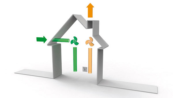
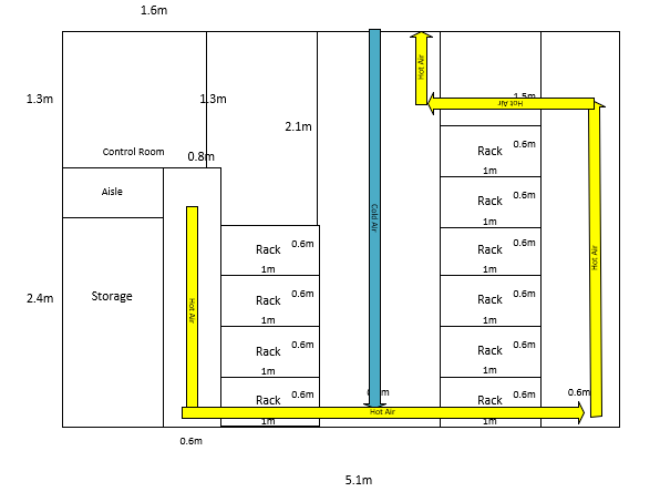
It is planned to have two fans - an inlet and an outlet - for redundancy purposes. As cooled air tends to fall and heat tends to rise, the inlet and outlet pipes will be located at different heights. It is also worth noting that the outlet system does not require a filter.
Other details to consider include how to prevent bugs from entering the pipes, providing easy access for filter cleaning, and exploring the possibility of reusing the heated air, which will be discussed further at a later stage.
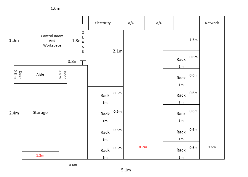
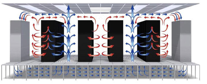
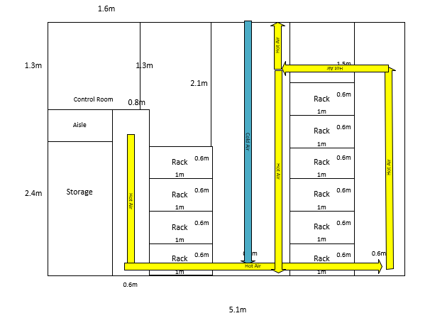
After reviewing the layout design for my data center, I have decided to have a single inlet pipe located in the center of the room. The two server racks will face inwards towards the pipe, allowing them to draw in the cold air and exhaust it towards the wall. As the heated air rises, it will be picked up by the outlet pipes located at a higher height.
To ensure sufficient cooling and ease of construction, I have decided to have one outlet port for every 1.5 racks, which should provide adequate ventilation.
Ventilation Fan
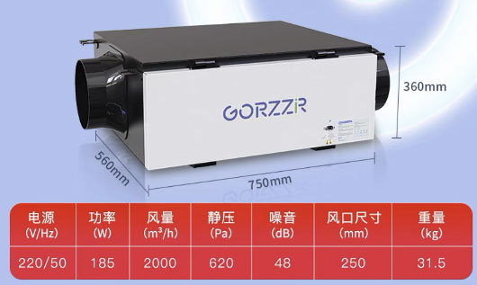
The ventilation fan is the core component of this system. Based on the room capacity (4.8 x 5.1 x 4.5 = 110 m3) and the desired ventilation rate (every 3 minutes), the fan model should be able to ventilate (60/3) x 110 = 2200 m3 per hour. The closest model that strikes a balance between energy efficiency (185W) and ventilation capacity (2000m3) is as follows:
Pipe & Port Size
Dimension of the Inlet Port
The ventilation fan requires a pipe with a diameter of 25cm to perform optimally. This results in a surface area of 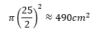
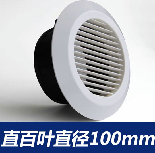
For each of the four inlet ports, the diameter should be approximately 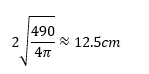 . As the closest model available is 10cm in diameter, I have decided to use this model. The reason for not using a larger model is to ensure a relatively higher wind pressure that can "push" the cold air down as quickly as possible.
Dimension of the Outlet Port
The same 10cm port was used for the outlet pipe because it was planned to be located higher up near the roof. As the hot air rises to the top of the room, it will be evenly blended. In this case, as long as there is an even intake rate and sufficient total airflow, the diameter of the outlet port does not significantly impact the performance. Additionally, using the same model for both inlet and outlet ports provides ease of installation and maintenance.
Finalizing Design & Purchase
Support
Due to the estimated weight of the pipes, mounting them all on the roof is considered a risk. To address this issue, I have decided to route most of the pipes along the wall, where a stand can be mounted to provide additional support. For those pipes that cannot be mounted on the wall, I will try to minimize the number of joints and bind them with another pipe that has minimal joints to increase its strength.
Control
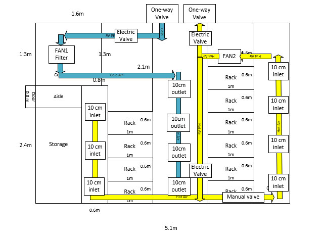
The inlet and outlet pipes may need to be closed during certain circumstances, such as during the winter or when air conditioning is active. To facilitate this, I have decided to install electric valves for both pipes, as the height may not be conducive to manual actions. One-way valves will also be put in place to prevent reverse wind flow.
An additional manual valve has been installed in the middle of the two connected outlet pipes. The plan is to close this valve when only half of the racks are active. As this valve will be rarely used, an electrical model is not necessary.
Extra
During the finalization of the design, I have discovered several additional benefits of this solution. Firstly, by placing the inlet fan directly on top of the control room, filter replacement no longer requires access to the actual server room. Secondly, I can redirect the hot air to other rooms instead of outside. This will keep other rooms relatively warm during the winter, potentially reducing heating costs when no one is present.
Fail-Safe
The fail-safe mechanism for the system is provided by the two fans - one inlet and one outlet. As the data center is a closed and sealed room, it is sufficient to have only one fan running at a time to provide airflow. In the event of a fan failure, we can rely on the other fan while fixing the issue.
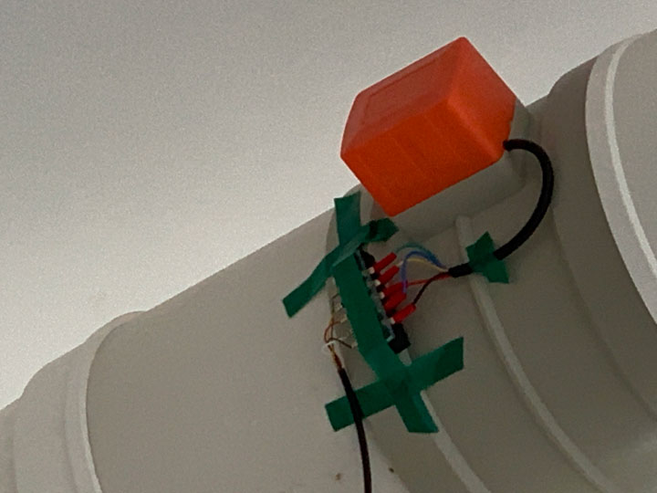
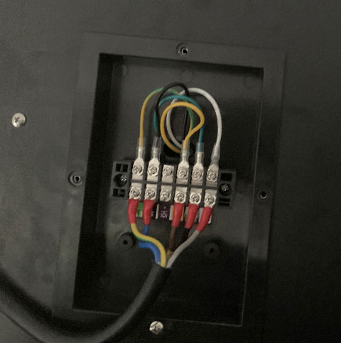
All electrical equipment, such as valves and fans, have been connected via a small circuit box. In addition to providing a clear definition of different electrical lines, this box also disconnects the power cable in the event of a device or pipe falling.
Finalizing
Based on the calculated dimensions and requirements, the final ventilation design is as follows: .
With this design, the total length of pipes of different diameters and types of joints have been calculated. As the purchase may take some time to arrive, several additional parts of each type have been bought in case of any issues during installation.
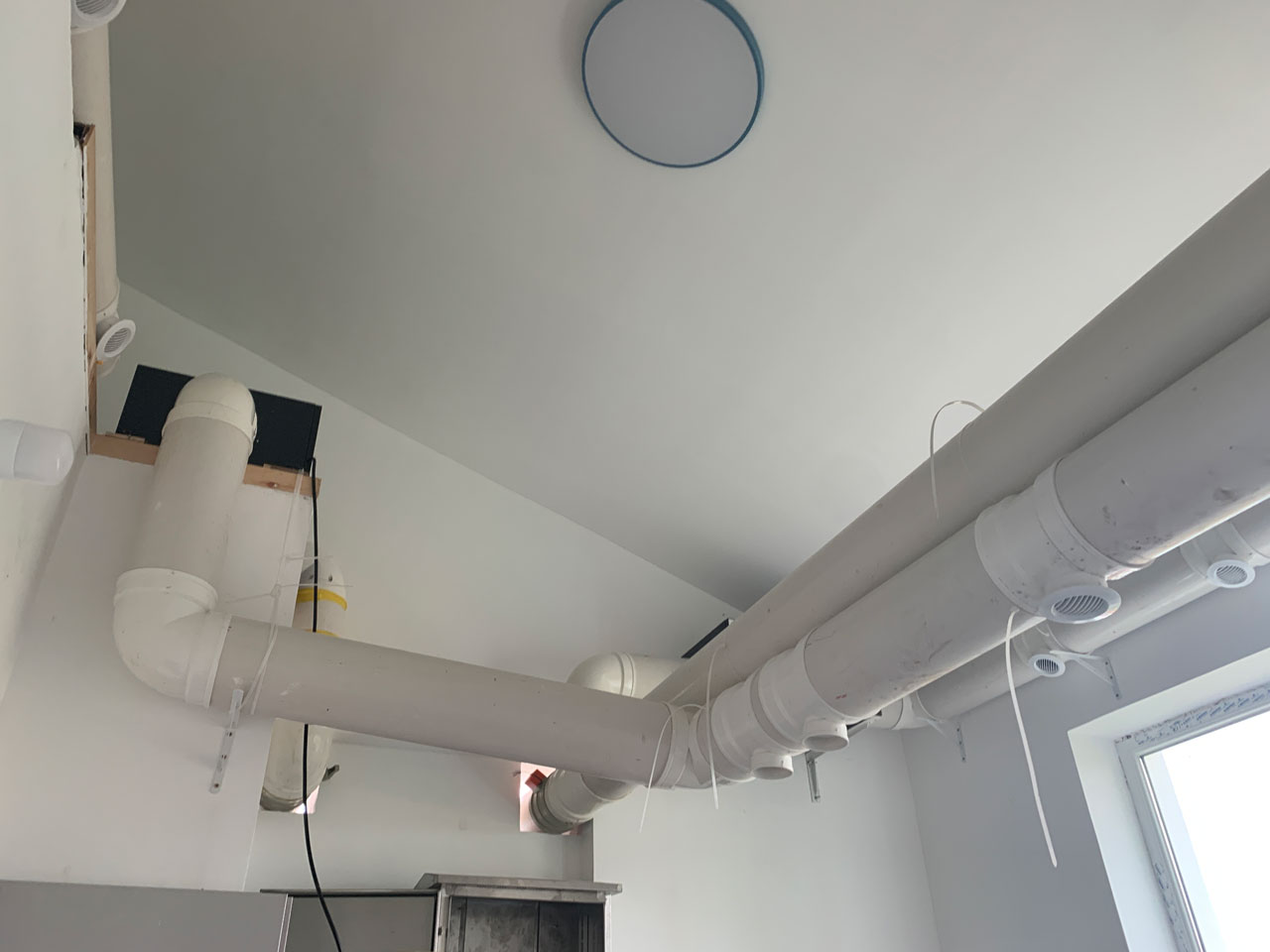
Material & Installtion
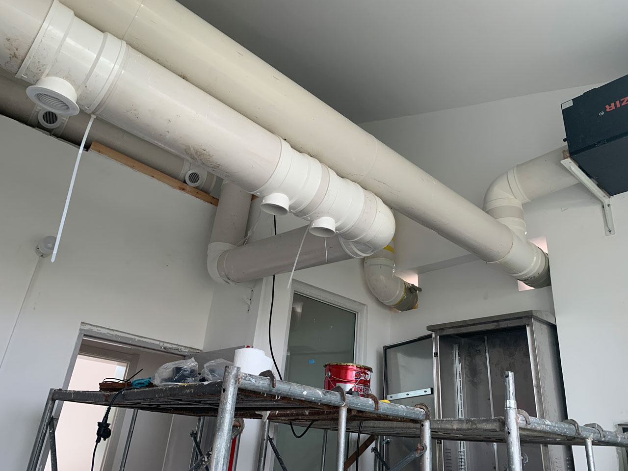
Installation can be a challenge, given the number of large PVC pipes and related joints that have been purchased. Extra care must be taken when cutting the pipes, as cutting them too short would leave no room for adjustment. The limited amount of extra length available for making errors further compounds this issue.
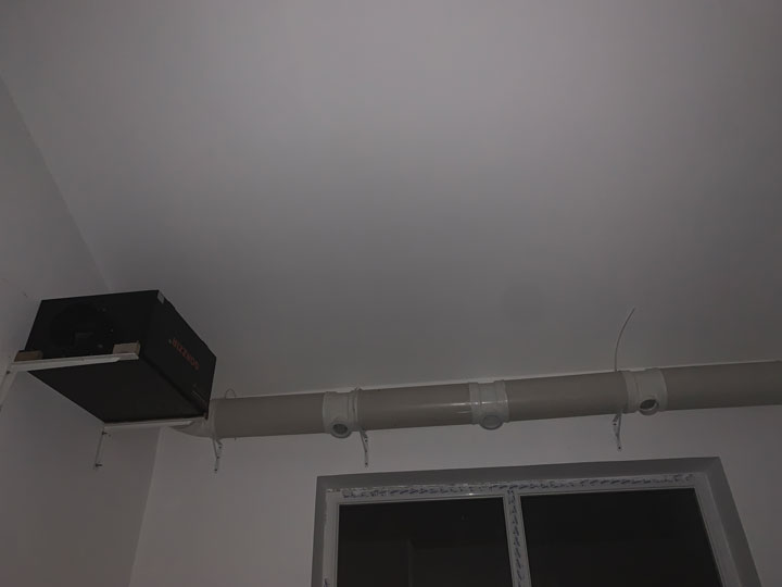
The weight of these pipes necessitated the need for construction workers to assist with installation onto the wall. To increase efficiency, I cut and assembled sub-parts outside on the ground in advance. Despite this, final installation still took around two days to complete.
All power and control cables, on the other hand, were finished on my own in a later stage where electricity was installed.
Outcome
At the time of creating this page, my datacenter has been running smoothly for almost a year, with the ventilation system functioning without any issues. This is not unexpected, given the amount of work and calculation that went into the design and installation process. One surprise has been the ability to turn off the ventilation completely during the winter without any problems. This may be due to the current number of servers and load not producing as much heat as initially anticipated.